Hardware
LED strip
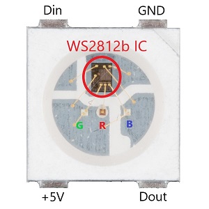
The most important part of the hardware is the LED strip. The choice is the WS2812(b) type because currently this is the most popular and widely available LED chip. It also means that it's cheap, and it's easy to find libraries to control it. Thanks to its popularity this type of LED is not only available in strip format but also in rings, matrix and strings which can be used to decorate a Christmas tree. This provides a wide variety of applications.
The most important aspect of choosing this chip that it's addressable which means that the single LEDs on the strip can be controlled independently of each other. There is a very tiny integrated circuit next to each LED which processes the digital signal and controls the red, green and blue lights.
Digital signal
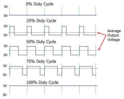
Interestingly while on a not addressable RGB LED strip there are 4 or 5 wires, on this type of strip there are only 3. Two of them are responsible for the 5V power and the third one carries all the data that is necessary for all the LEDs on the strip. To understand how the data line works it's necessary to understand what is PWM(Pulse-width modulation). The PWM signal is a type of digital signal where the voltage alternates between a high and a low value. Ideally there is no in-between value.
PWM
A very important property of the signal is that how much time it stays high and low. In case these time frames repeat cyclically the type of the signal can be expressed with its Duty Cycle. This is a percentage value that shows how much part of the time the signal has the high value. This type of signal has a huge number of different applications. For example if the requirement is to control the rotation speed of an electric engine(e.g.: fan) the PWM signal is a perfect way to do that. In case of a 100% duty cycle the rotation speed is the maximum. If the duty cycle goes down to 50% the rotation speed decreases significantly. However, the duty cycle is not directly proportional to the rotation speed so it cannot be said that the speed is halved compared to the maximum.
Controlling the LEDs
A PWM signal is necessary to control the LEDs. The PWM signal controls the red, green and blue lights in an LED and that's how colors can be changed. For example if the green and the blue lights are on maximum brightness and the red is completely turned off it is perceived as a bright cyan. The brightness of a single light can be controlled with an 8 bit value which makes 256 different options. So it takes 24 bits to control the color of a whole LED. It means it takes as much data as 24 times the number of LEDs on the strip to control all of them. The bits can be set with the precise timing of the PWM signal alternation. The exact timings are specified on the 3rd and 4th pages of the data sheet(https://cdn-shop.adafruit.com/datasheets/WS2812B.pdf). According to that, to send a 0 value the signal has to be high for T0H(0,4 us) then has to be low for T0L(0,85 us). To send a 1 value it has to be high for T1H(0,8 us) and has to be low for T1L(0,45 us). For every alternation there is a 150 ns error threshold.
The signal is processed by the first LED on the strip using the first 24 bits and it changes its color based on that. The rest of the signal is sent towards the next LED using a signal amplifier. The next LED also "takes down" 24 bits and transmits the left and so on. If the data is not enough for all the LEDs, those at the end will not light up at all. In case there is more data than necessary it does not do anything wrong. The useful data is used and the rest is ignored. If the color of an LED needs to be updated all the data has to be sent over again with the change of that specific 24 bits. Before new data can be sent a RESET signal needs to happen. That means that the digital signal has to be low for at least 50 us. This triggers the mechanism to read and apply the upcoming data again.
Since producing the data takes time the actual color change of the LED is delayed. In case of a really long strip it might be detected by the human eye. Producing a single bit takes 1,25 us. 1 LED need 24 bit which is 30 us. In case of 1000 LEDs it is 30 ms. That is somewhere around the human eye detection(https://news.mit.edu/2014/in-the-blink-of-an-eye-0116). This needs to be considered when designing the layout of the strips.
Any type of Raspberry has 2 output pins which are able to produce PWM signal which means 1 Raspberry is able to control two different LED strips. Also, the system is able to control and synchronize multiple Raspberrys, and it does not have a theoretical limit.
Some power consumption testing
2 meter WS2812: full white: 4.18 A 2 meter WS2812 80% white: 3.35A 2 meter WS2812 0.5 white 2.14 A 2 meter WS2812 full red: 1.48A 2 meter WS2812 full blue: 1.48A 2 meter WS2812 full green: 1.48A